Setup a custom operating room#
How to Acquire or Create 3D Models of Operating Rooms#
This tutorial covers the essential methods for acquiring or creating 3D models of operating room (OR) assets. These are the key steps:
-
Define the Asset List. Identify which OR assets you need. Common assets include:
-
Monitors and anaesthesia machines
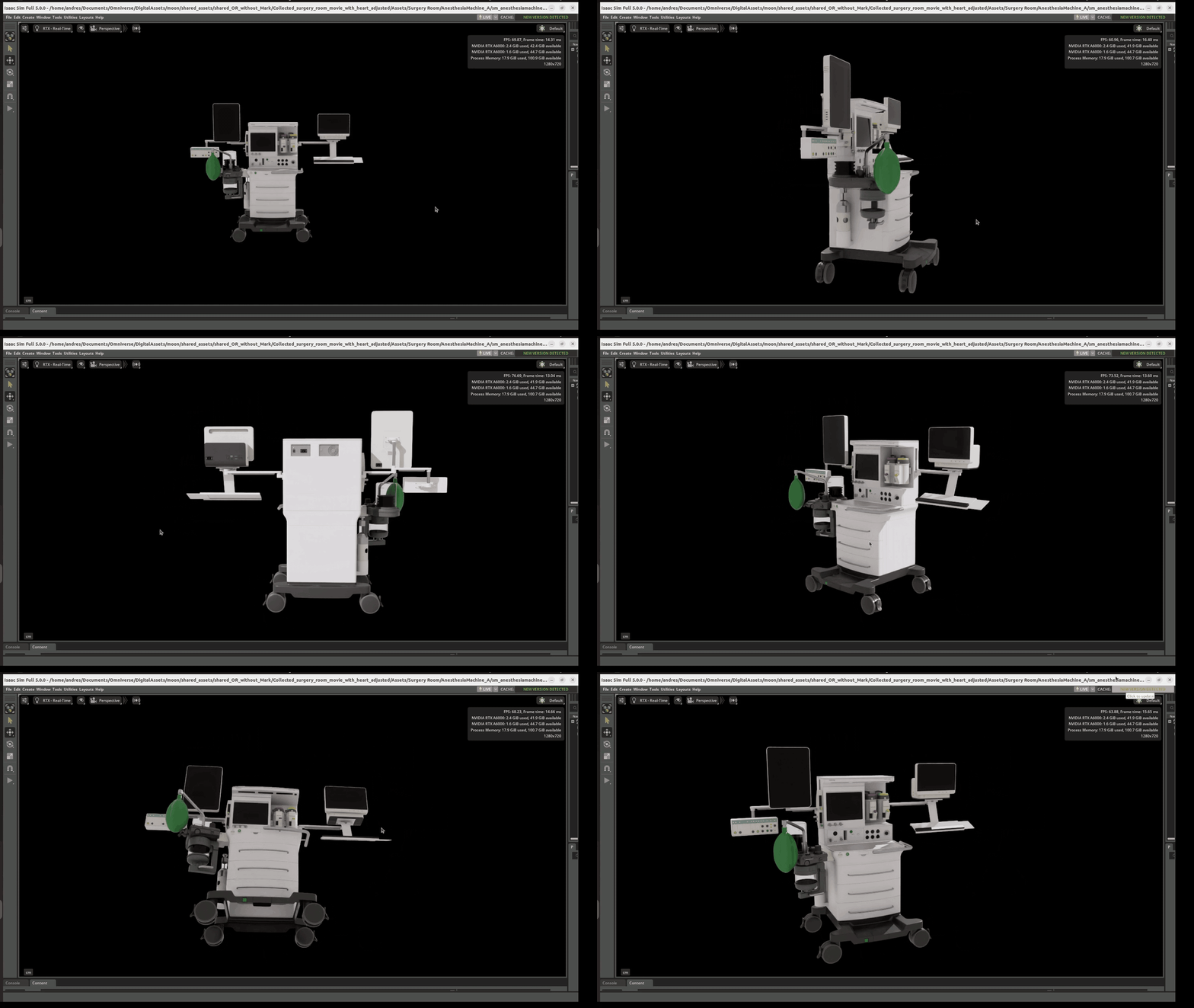
 This is a low‑res preview. You can download the original high‑resolution version here:
   [Download high‑res Anesthesia Machine GIF](https://developer.download.nvidia.com/assets/Clara/i4h/operating_room/anesthesiamachine_highres.gif)
-
Surgical lights
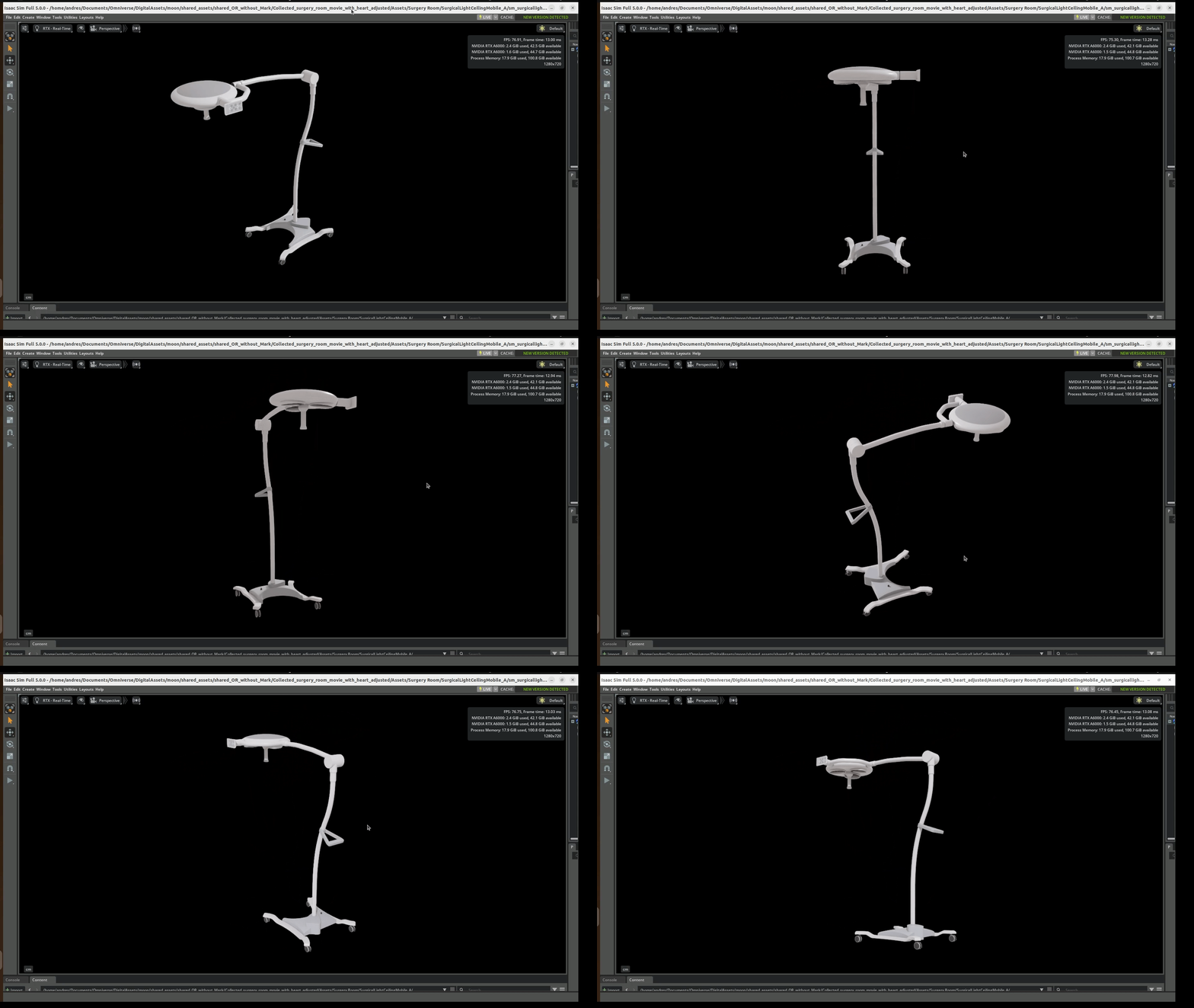
This is a low‑res preview. You can download the original high‑resolution version here: Download high‑res Surgical Lights GIF
-
Operating tables
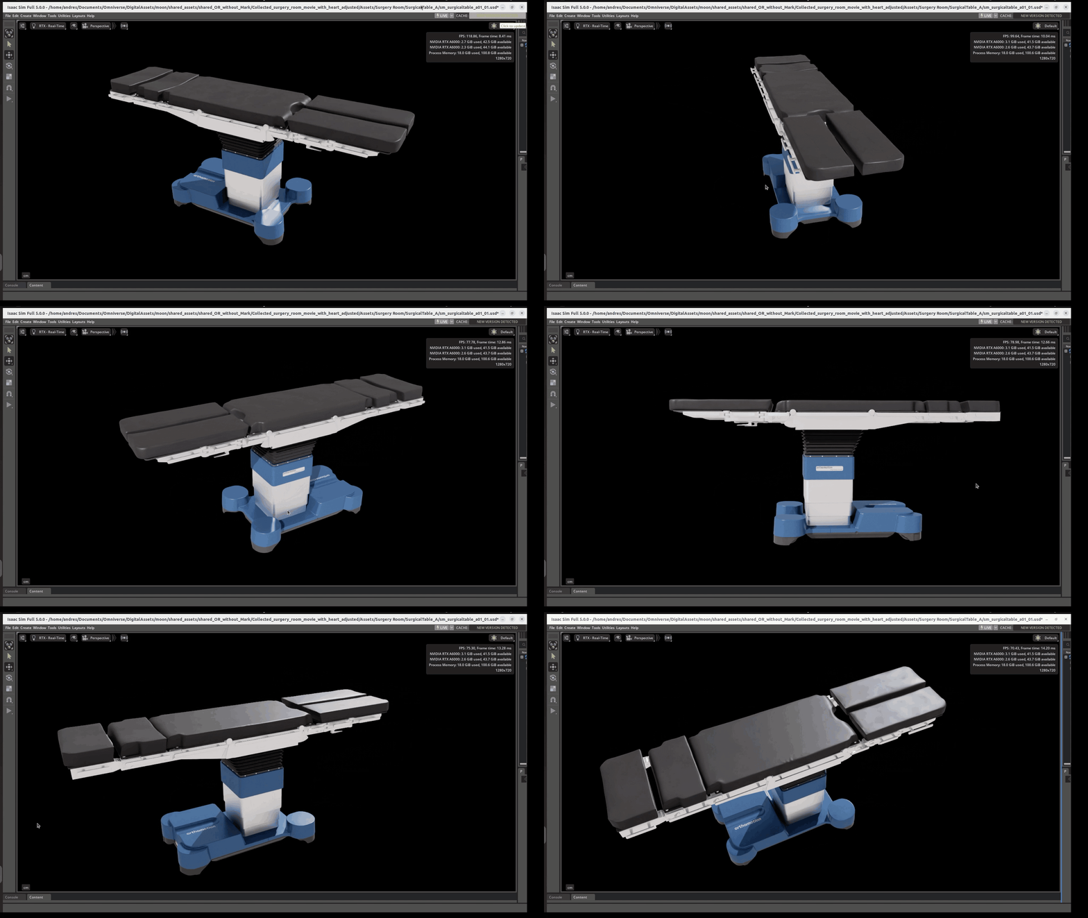
This is a low‑res preview. You can download the original high‑resolution version here: Download high‑res Surgical Table GIF
-
Ultrasound machine
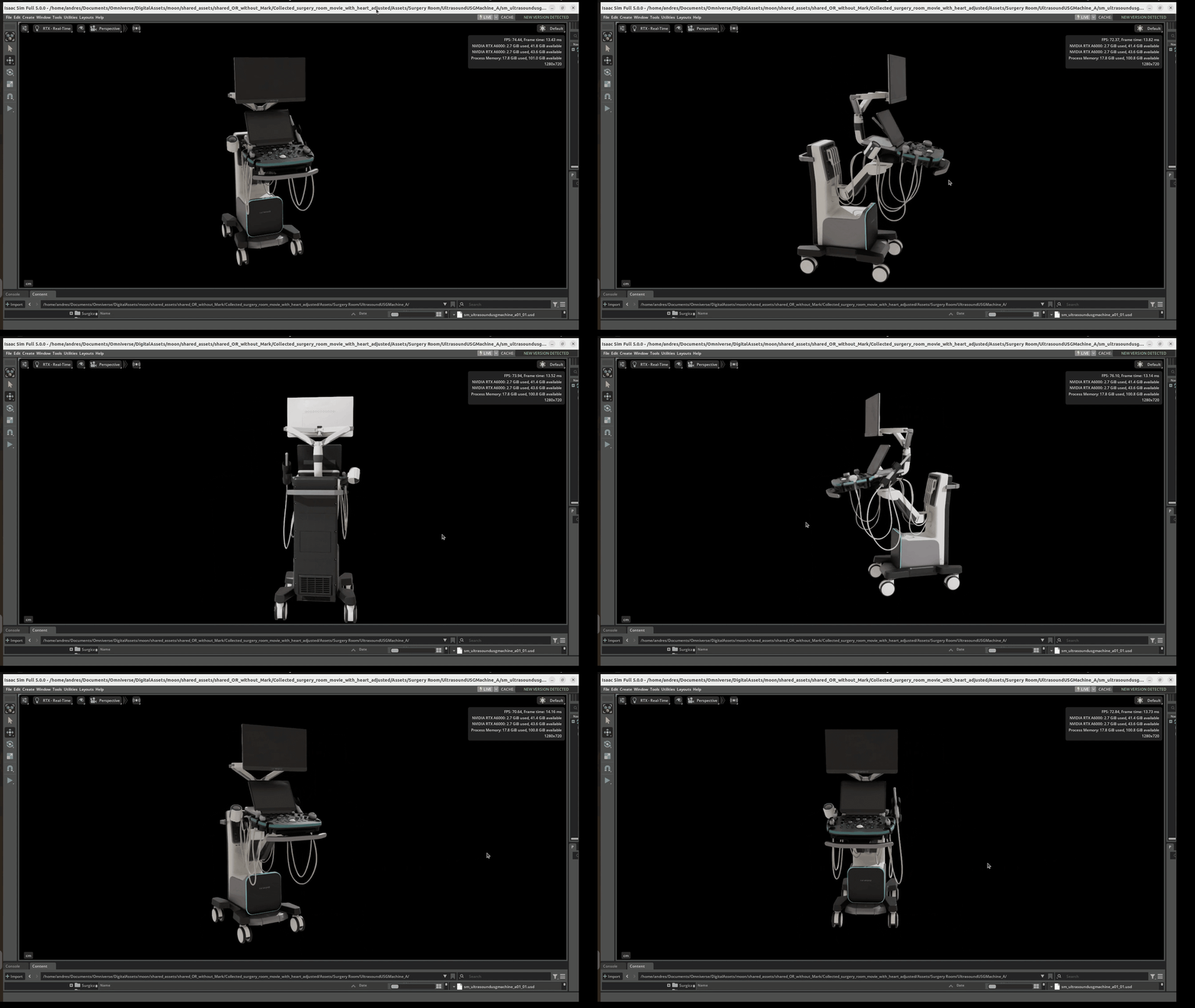
This is a low‑res preview. You can download the original high‑resolution version here: Download high‑res Ultrasound Machine GIF
-
Pre-made 3D Assets - Isaac For Healthcare Operating Room Use asset libraries for common OR components, devices, general anatomy, and props (https://github.com/isaac-for-healthcare/i4h-asset-catalog/blob/main/i4h_asset_helper/README.md)
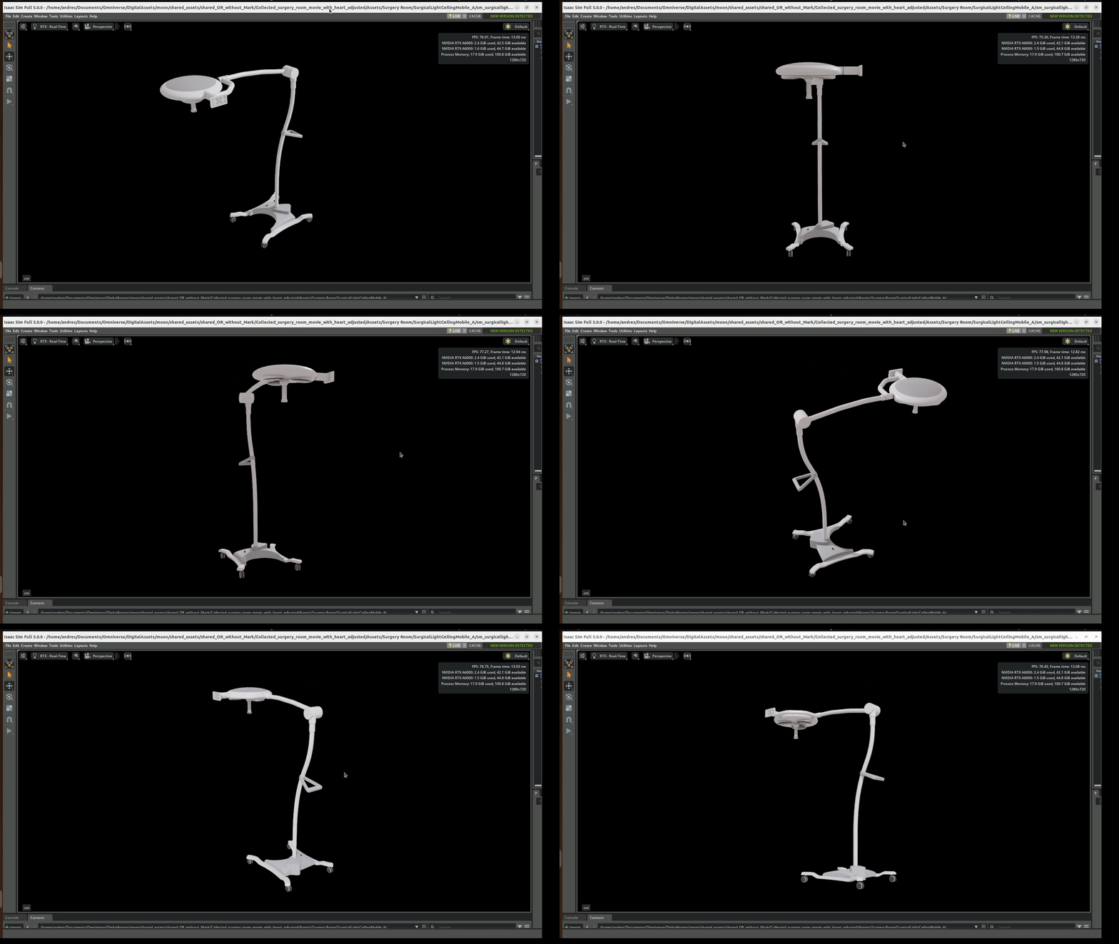
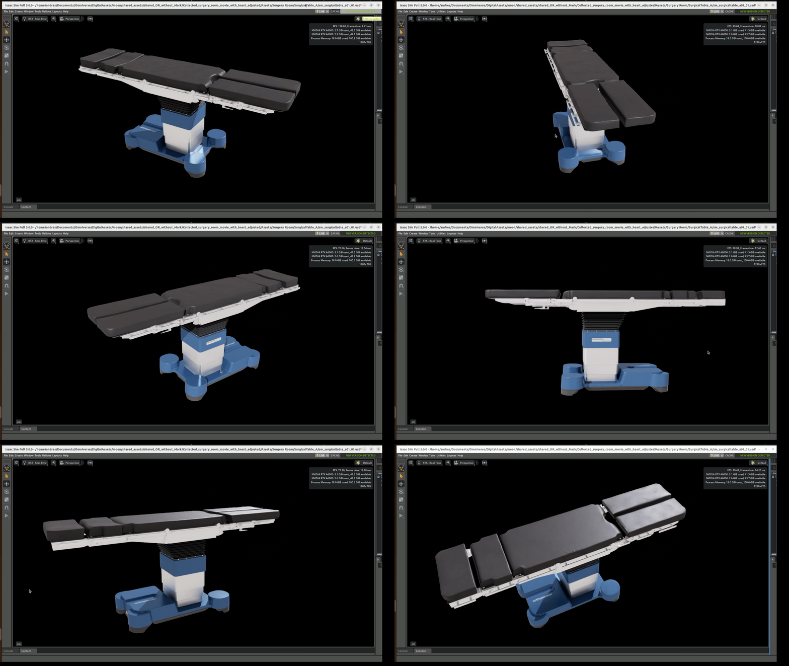
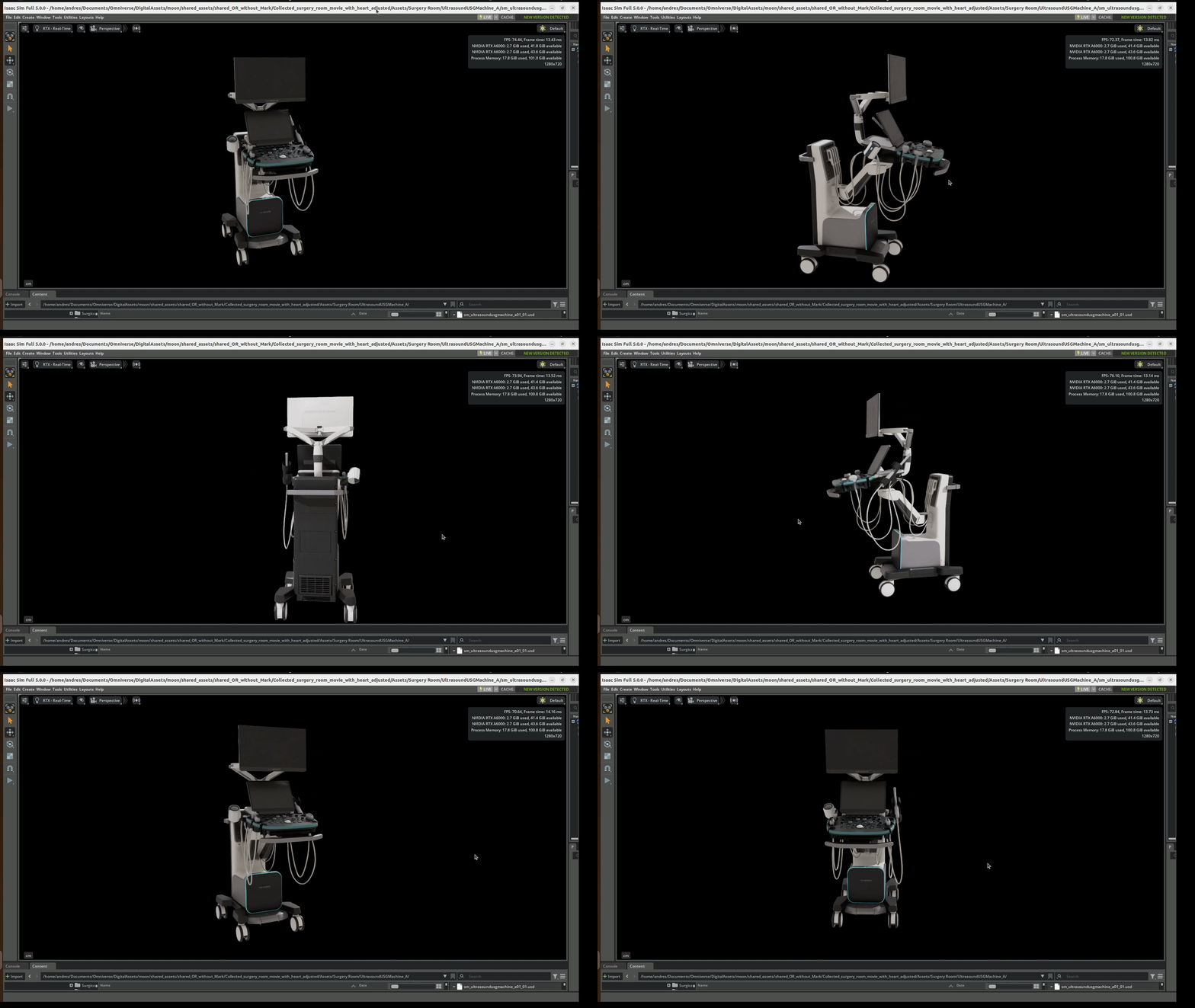
Where to find:
-
Follow the instructions in Asset Catalog Documentation to install the assets helper, and then run
i4h-asset-retrieve --sub-path Props/shared_OR_without_Markto download the assets.
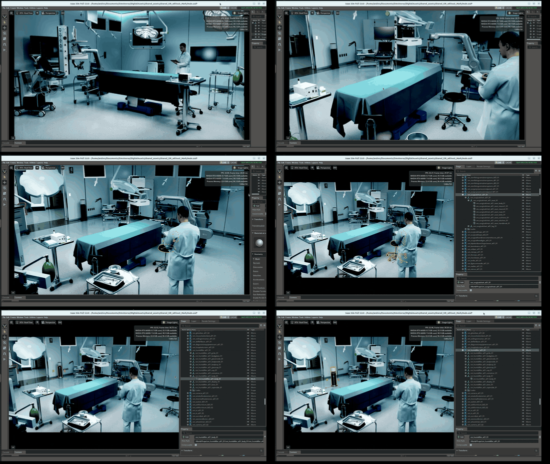
This is a low‑res preview. You can download the original high‑resolution version here: Download high‑res Public OR NVIDIA GIF
-
Ways to Acquire more 3D Models
-
Download Existing 3D Models
Use professional 3D asset marketplaces such as TurboSquid (https://www.turbosquid.com/), Sketchfab (https://sketchfab.com/) or CGTrader (https://www.cgtrader.com/). Search for "operating room", "surgical equipment", etc. Many sites offer models in various formats (OBJ, FBX, STL, etc.) for direct use or modification. Check public domain or open-license repositories for free models, though quality and detail vary.
-
Purchase from Specialized Medical Suppliers
Some medical equipment manufacturers offer digital twins or CAD files of their real-world equipment, especially for architectural or training simulation use. i.e.: https://www.hillrom.com/en/services/construction/design-files/
Notes:
1. Supported formats: Omniverse supports most CAD formats, e.g. SolidWorks Files (\*.SLDPRT, \*.SLDASM), STL Files (\*.STL), ACIS Files (\*.SAT, \*.SAB), Autodesk Inventor Files (\*.IPT, \*.IAM), Autodesk 3DS Files (\*.3DS), Step/Iges (\*.STEP, \*.IGES), etc 2. How to convert CAD into OpenUSD using Isaac Sim: 1. Download the CAD file 2. Open latest Isaac Sim (v 5.0.0) 3. Search the file 4. Right click on the file, then Convert to USD 5. The converted USD file appears in the stage; locate originals nearby. 6. If needed, assign materials/shaders 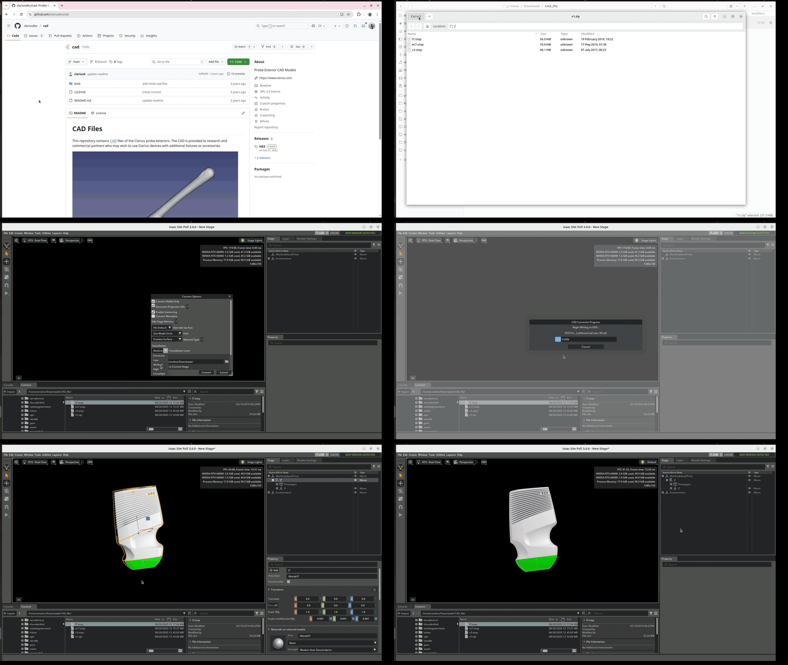 This is a low‑res preview. You can download the original high‑resolution version here: [Download high‑res Export CAD model GIF](https://developer.download.nvidia.com/assets/Clara/i4h/operating_room/export_CAD_model_highres.gif)Further learning: CAD converter extension: https://docs.omniverse.nvidia.com/extensions/latest/ext_cad-converter.html
-
Create Custom 3D Models using 3D Modeling Software:
Use tools like Blender (free/open-source), Autodesk 3ds Max, Maya, or Cinema 4D. Gather as many reference images, blueprints, or dimensions of the assets as possible. Model each asset to scale for realistic simulation or visualization. Texture and shade assets to closely match real-world appearance. Further information: https://youtu.be/EsufneMOvWA?si=TQNgdZHrarUMdPuq
- Photogrammetry or 3D Scanning
If you have physical access to OR assets, consider capturing them via photogrammetry (taking multiple photos from all angles, then using software like RealityCapture or Agisoft Metashape to generate a 3D mesh) or using a 3D scanner for fast, high-detail models.
Steps:
 * **Capture imagery**
   Use a camera (even a phone). Take 40–100+ overlapping, sharp photos all around the object/environment, ensuring each photo overlaps the next by at least 60–80%. Walk around the object, keeping the camera at similar height, then repeat higher or lower, to get all surfaces (including top, sides, back).
   Lighting and sharpness matter; avoid motion blur.
 * **Process with photogrammetry software**
   Recommended tools: Meshroom, RealityCapture, Metashape, or COLMAP.
   Meshroom workflow:
     Load images; start the pipeline. Structure-from-Motion estimates camera pose and a sparse point cloud. Multi-View Stereo (MVS) generates a dense mesh; results are OBJ file with MTL and textures.
     COLMAP/Metashape: similar workflow; camera calibration → feature matching → dense reconstruction.
 * **File Formats and Optimization**
   Export models in commonly supported game/visualization formats (e.g., FBX, OBJ, GLTF).
   Optimize for polygon count and texture size based on your target platform (e.g., real-time VR, architectural render, etc.).
   Meshroom and others output .OBJ, .FBX, .PLY, or .USD files suitable for use in Omniverse. Clean up mesh in Blender or similar if needed.

   **Further info:** [Photogrammetry - 3D scan with just your phone/camera](https://youtu.be/ye-C-OOFsX8?si=MGom5GSgUnfeVuuE)
- Licensing and Permissions
Ensure you have commercial rights for any downloaded or purchased assets if you plan to use them in commercial applications. If using patient-specific or proprietary equipment, check legal or contractual restrictions.
Rigging Robots in Isaac Sim: Steps, Tools, and Verification#
Rigging in Isaac Sim is the process of transforming a static 3D model (geometry/CAD files) of a robot into a fully articulated system that can be controlled and simulated physically. This involves defining its moving parts, the joints that connect them, and their physical properties so it can be driven by Isaac Sim's APIs. This is fundamentally different from avatar rigging for animation, which focuses on creating a visual skeleton for mesh deformation and lifelike movement – not physical interactions. Robot rigging prioritizes realism in dynamics, using articulations and a physics engine, while avatar rigging uses skeletons and animation retargeting to achieve believable visuals, usually for games or cinematic purposes.
This tutorial provides a quick overview of robot rigging for simulation – not avatar rigging – so all guidance centers around physics-driven articulation, control and verification.
The Rigging Process: Key Steps#
The core workflow for rigging a robot in Isaac Sim involves several critical steps, from organizing the model's structure to defining its physical behavior.
- Hierarchy Organization
Before any physics properties are added, the robot's components must be logically grouped. All parts that move together as a single rigid link (e.g., the main chassis of a forklift) are placed under a single parent prim, typically an XForm. This creates a parent-child hierarchy that dictates how parts are connected and move relative to one another.
Tutorial 2: Assemble a Simple Robot
- Collision Mesh Assignment
To prevent the robot from passing through itself or other objects, each moving part needs a collision mesh. Isaac Sim offers several methods for creating these physics representations: Convex Hull/Decomposition: These are common approximations for complex shapes, creating a simplified physical boundary around the mesh. Primitive Shapes: For parts like wheels, using simple shapes like cylinders for the collider ensures smooth rolling motion, avoiding bumps that can arise from complex mesh colliders. Tutorial 3: Articulate a Simple Robot
- Joint and Drive Creation
This is the central part of rigging, where motion constraints are defined: 1. Joints: Physics joints are created between different parts of the hierarchy to define how they can move relative to each other. Common types include Revolute Joints for rotational motion (like wheels or arm joints) and Prismatic Joints for linear motion (like a forklift's lift). 2. Drives: To control the joints, a drive is added. Angular Drives control revolute joints, and Linear Drives control prismatic joints. Here, you set key parameters like Stiffness and Damping, which determine how the joint responds to forces and commands.
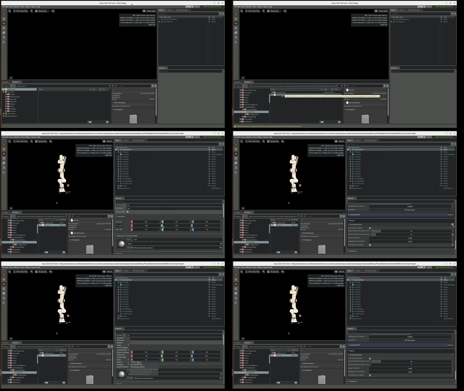
- Articulation Root Finally, the entire assembly of links and joints is defined as a single entity by adding an Articulation Root to the robot's base prim. This tells the physics engine to treat the robot as a single articulated system, which is more efficient to solve and essential for stable simulation. It also allows you to disable self-collisions among the robot's parts if needed.
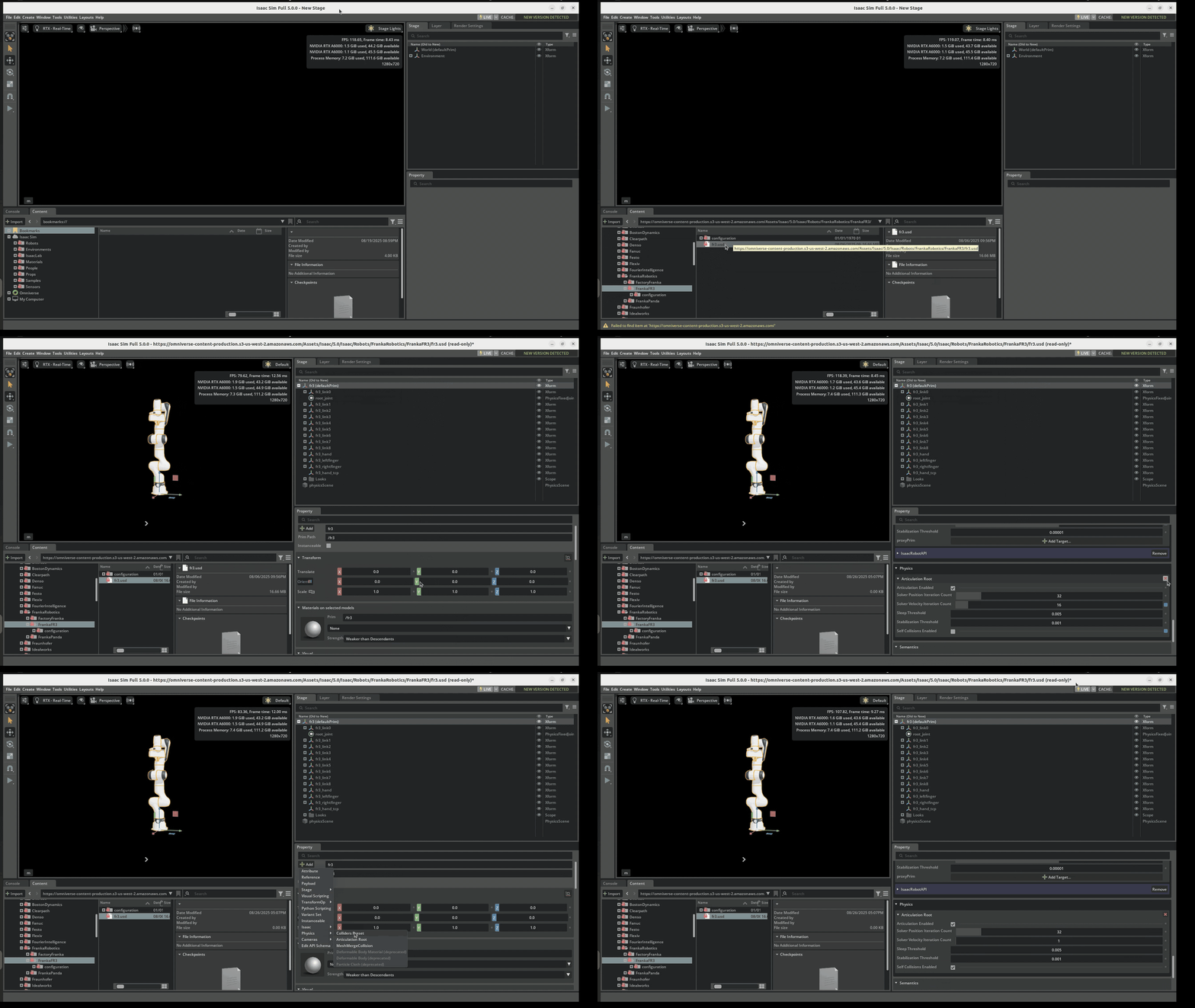
This is a low‑res preview. You can download the original high‑resolution version here: Download high‑res Articulation Root GIF
- Verification Tools and Extensions
Isaac Sim provides specialized extensions and built-in tools to assist with and verify the rigging process.
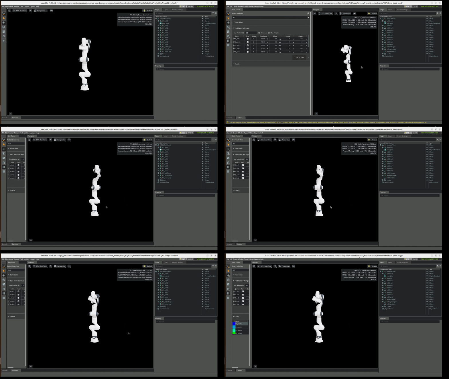
Gain Tuner: built-in tool for tuning and testing joint gains; accessible via Tools > Robotics > Asset Editors > Gain Tuner; run sinusoidal and step tests per joint or sequences.
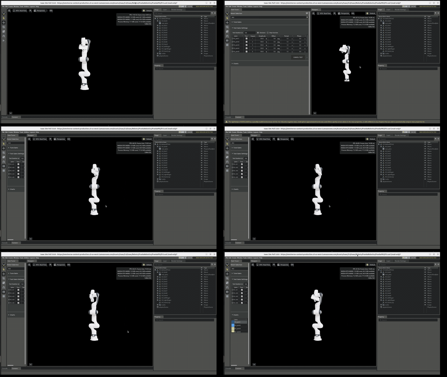
This is a low‑res preview. You can download the original high‑resolution version here: Download high‑res Gain Tuner GIF
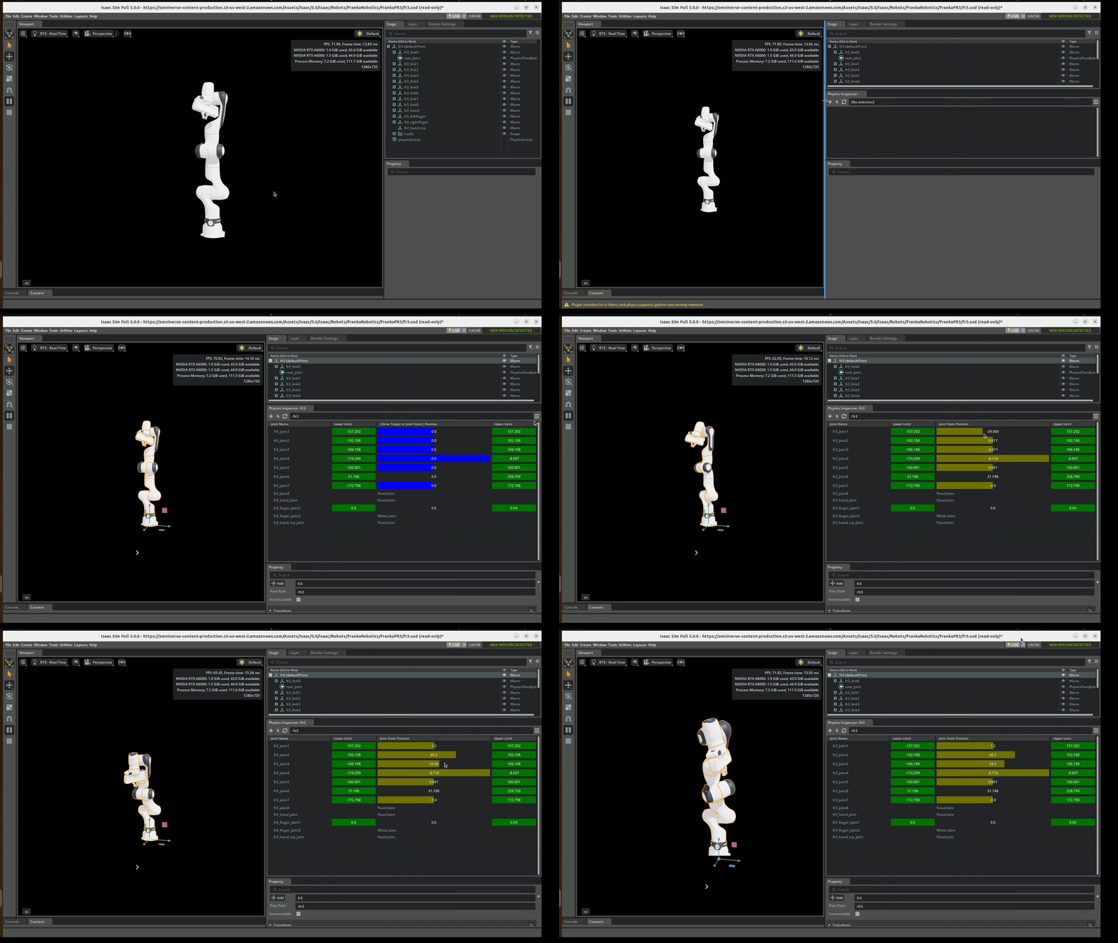
Physics debugging/inspection: Use Physics Inspector and related Isaac Sim diagnostics to confirm joints, limits, masses, and drive responses.
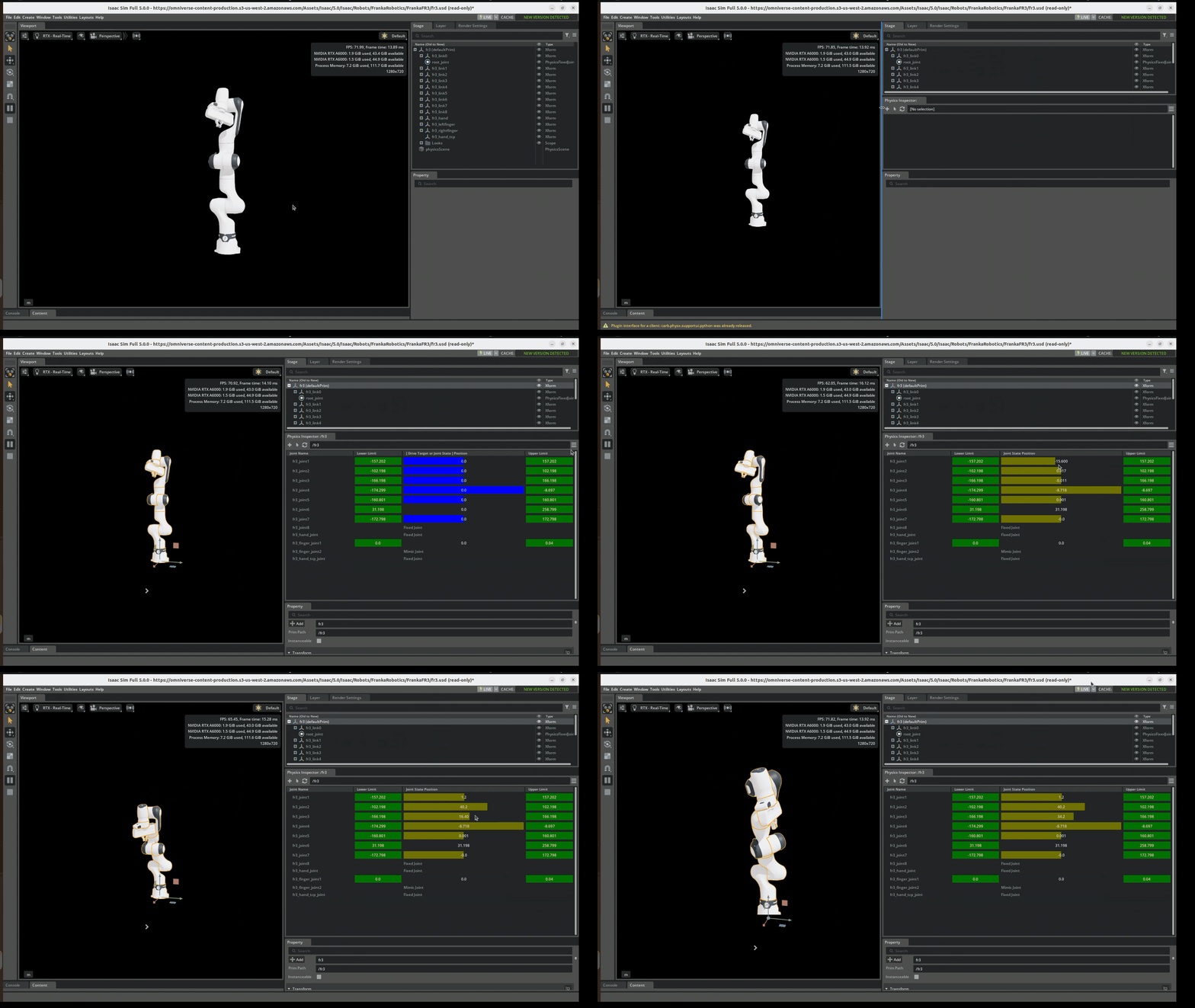
This is a low‑res preview. You can download the original high‑resolution version here: Download high‑res Physics Inspector GIF
References: